Toyota Multi-Mode Transmission
Toyota’s Multi-Mode transmission (MMT) has been around for over seven years; fitted to the Aygo, Yaris and Corolla. You will find it being referred to as an automatic, and it is, but it shouldn’t be confused with traditional automatic transmissions. Traditional automatics provide smooth driving characteristics due to a transmission equipped with epicyclical gears, hydraulic clutches and a torque converter; the MMT has none of these features. This article looks at the concept, how it works and some of the issues that arise for the technician.
Toyota’s MMT is an attempt to provide a small, efficient automatic transmission without all the energy sapping complexity of the previously mentioned hydramatic derivatives. The MMT is in effect a conventional five-speed countershaft gearbox with a robot employed to do all the shifting and clutch work. It all sounds fairly simple in a 21st century context, but it is only when we consider how a driver controls the clutch and gearbox, that we begin to appreciate how complicated the whole process is.
This system uses permanent magnetic motors to control the clutch and gears. There are three actuators; the shift and select actuators which move the selector rod in the same way as the ‘H’ movement of a manual gearbox, and the clutch actuator which moves the clutch pushrod. The motor’s torque, speed and direction are monitored and controlled by Pulse Width Modulation (PWM) and polarity. Hall sensors feed back to the transmission control module the speed and position of the actuators.
The purpose is to simulate a driver’s use of the clutch and gears and prevent misuse. Think about the degree of control required to drive a vehicle onto a ramp. The driver has to sense forwards or backwards movement, acceleration, the clutch biting point and engine speed etc. For the Transmission Control Module (TCM) to do this, it requires information from various sensors.
Wheel Speed Sensors
The TCM needs to know the speed of the vehicle, the direction of travel and be able to pick up the smallest movements. Traditional reductor type sensors cannot do this. MMT equipped vehicles are fitted with Magnetic Resistance Element (MRE) digital sensors which have the advantage of providing a signal from rest. The sensor detects movement, speed and direction. The wheel speed sensors are part of the ABS/VSC system which gather the information and pass it to the TCM.
For all this information to come together there has to be com brake control modules. This is done by a combination of a TCM and a CAN BUS network between the Engine Control Module system to communicate with and control systems in other area.
The system is programmed to monitor and ‘learn’ operational changes. The TCM actuates the clutch and measures the end to end travel. The clutch biting point is monitored on actuation to account for centre plate wear.
This is monitored to account for wear in the selectors and the baulk rings in the synchromesh. It also allows the system to re-attempt a gear selection if gear baulking occurs at the first attempt.
The Controls This is a two pedal operation system, there is no clutch pedal. There are two modes, Automatic (E) and Manual.
In E Mode, (which is the equivalent to a fully automatic ‘D’ mode) the TCM calculates when to change gears taking into account the driving conditions and the driver’s driving style. Up-shifting can take place with the accelerator fully depressed; the ECM takes control of the throttle. Hard acceleration produces a kick down effect by the clutch Actuator.
In Manual Mode, the driver decides when to change gears using the gearstick. The TCM then automatically operates the gear shifting mechanism and the clutch, however, the transmission will automatically change down a gear to prevent the engine labouring or change up a gear to prevent engine over revving.
When the brake pedal is not depressed and 1st, 2nd or reverse is selected, the clutch is half-engaged, even if the accelerator pedal is not depressed. As a result, the vehicle can creep slowly like an automatic transmission vehicle; this will assist the vehicle in preparing to move. The take off assist control is cancelled while the parking brake switch is ON.
There is no ‘p’ (park) function, but it is possible to stop the engine with a gear engaged (to park on a slope for instance). When this happens, the driver needs to press the brake to allow the engine to be restarted.
Technical Feature – Shift Lock Solenoid
This is built into the gear selector mechanism; if the shift lever is kept in the ‘N’ position for 2 seconds with the brake pedal released, while the vehicle is at rest, the transmission control ECU locks the shift lever to prevent improper shift lever operation. The shift lever is unlocked when the brake pedal is depressed.
A self-adjusting clutch mechanism is fitted to the cover plate. This reduces the need for large clutch actuator travel to account for wear on the centre plate; it is a simple ratchet and pawl device.
Firstly remember that this is a conventional five-speed gearbox and that all the problems associated with such a device can occur on the MMT. Should the car break down it may do so with a gear engaged; by carefully removing the select and shift sensors, the slotted ends of the shafts are exposed; neutral can be selected by turning the shafts.
With so many sensors and actuators involved, a whole set of parameters are generated. Obviously you will need a scan tool that will allow you to access the Digital Trouble Code (DTC), data and perform actuations to assess the performance of the system. The G-Scan allows full access to the system to diagnose problems associated with the control system. Gear selection can be actuated and data monitored at the same time to aid diagnosis.
Under normal conditions with the clutch engaged and the transmission in neutral, the clutch is slightly preloaded. Consequently when replacing the clutch, or clutch actuator, the clutch must be put into a default position with the load removed or damage will occur. This is known as the clamp position; this can be done with the G-Scan, or manually using our technical bulletin.
When any of the actuators, sensors, clutch components, transmission assembly or TCM are replaced, the system must be initialised. Initialisation removes all learned values from the TCM memory and relearns the clutch biting point and selector mechanism movement. This too can be done with the G-Scan, or manually using our technical bulletin. (removing the battery negative will not erase the TCM memory). When the vehicle is started and drive is engaged the vehicle should creep forward, this confirms the initialisation has been successful.
This sounds complicated but it is in fact just a test drive; it allows the system to fine tune the clutch actuation and gear change. This will happen naturally in the hands of your customer, but in order to hand the vehicle back in optimum condition, follow the procedure shown in our Technical Bulletin.
Water pump problems on the Aygo explained:
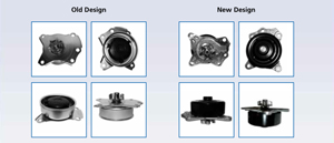 Following modifications made by the Original Equipment manufacturers, the water pump construction has now been changed from a pressed steel type body to a die-cast aluminum constructed body. This change in design has been made to improve reliability.
The original OE steel constructed water pump body is not as rigid as a die-cast alloy design, which could lead to excessive tolerance on the water pump mechanical seal and result in the water pump leaking over a period of time.
When replacing a steel type body water pump with the aluminum type, you must replace the original fitment bolts with the longer bolts which are included with the Blue Print pump. Using the original steel type body bolts with the aluminum body will cause fitment issues as the bolts will be too short and may lead to premature failure.
Clutch problems on the Aygo explained:
The Toyota Aygo, which is platform shared with the Citroën C1 and Peugeot 107, is known to suffer from premature clutch disc wear. Drivers also complain about clutch noise; this is attributed to release bearing ‘squeak’, which is caused by a worn clutch cover diaphragm spring and/or a broken release bearing tab – this may make it difficult to change gear and the clutch heavy.
Blue Print advises that if you are working on an Aygo, C1 or 107 that has symptoms relating to a worn clutch disc, then a complete clutch kit replacement is required. It is also recommended that if you are replacing the clutch kit, or the complaints relate to the symptoms highlighted above, then the clutch fork must also be checked and replaced if necessary. In this situation the increased effort required to change gear may result in stress fractures in the fork.
 Please note: The manufacturer has issued a service bulletin to highlight that the design of the fork has been improved to prevent future issues, therefore if you fit a new fork, make sure it’s the modified OE version.
A production change on the clutch fork took place in June 2013:
There was a second service bulletin issued by the manufacturer regarding premature clutch disc wear. To maximise the service life of the clutch disc, they have replaced the original 180mm diameter disc with the 190mm disc used on the Yaris (KSP90). Blue Print’s clutch kit ADT330246 for the above applications is only supplied with the 190mm clutch assembly.
Please note: With the larger clutch disc installed the clutch engagement point will be 15-20mm lower, which could be noticed by the driver. Also, because of the increase in diameter it is essential to check the condition of the flywheel and if required, replace it or have it professionally machined.
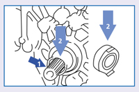
 When fitting the new release bearing you must follow these guidelines:
• Apply clutch spline grease only to the input shaft splines.
• Do not apply the grease to the release bearing or other parts of the input shaft.
Finally, the manufacturer issued a third bulletin which highlights that the lifetime of the clutch disc can be extended further, if in all instances, whether the vehicle is in for a service (every 9000 miles) or a clutch replacement, that the clutch pedal free play is checked and adjusted – if there is no free play, clutch disc wear increases.
The procedure to check and adjust clutch pedal free play:
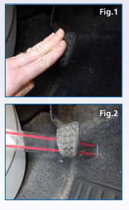
• Push the clutch pedal down by hand (Fig. 1) checking for smoothness of operation. Stiffness or roughness in operation will require further investigation to determine the root cause.
• Measuring the free play in the pedal can be done quickly and easily by applying gentle force to the pedal with your hand (approx 15-20Nm) until you feel the amount of pressure required increase. Measure the distance travelled by the pedal with a ruler – the amount of free play in the clutch pedal needs to be 23mm, +/- 5mm.
Adjusting the clutch cable:
• Pull the clutch outer cable until it is released from the Fixation Pin (approx 3mm).
• Rotate the Adjusting Nut to increase or decrease the free play as necessary (1 full turn of the Adjusting Nut is equivalent to about 6.5mm of pedal free play).
• Ensure the Adjusting Nut is locked back in place on the fixation pin after adjustment.
• Operate the clutch 2-3 times.
• Re-measure the clutch pedal free play and adjust as necessary.
Please Note: After adjustment, the clutch pedal may be higher than the brake pedal – this is normal.
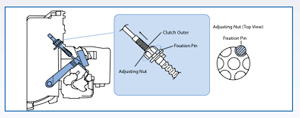





H, just trying to understand how the clutch cable is adjusted. in the description it advises to turn the plastic nut on the sleeve of the cable! so what is the metal nut for on the actual cable which pulls the release fork of the clutch. I thought this is what was used to adjust the clutch?
If you get stuck you can call the Blue Print technical helpline on 01622 833004.
I have a 2013 Aygo Fire MMT transmission which is playing up at 22000 miles. This article goes some way to explain the mechanics but should this be a quality issue or simply wear and tear a such low mileage?
It isn’t a new car anymore – and things go wrong on all vehicles, even Toyotas. An independent transmission specialist will typically diagnose the problem properly and charge a much better price than the franchise dealer. GW.